Note · Experiments · 8 min read
Three prints to a working part
A language model designed a 3D-printable part in Blender, a mount for my phone that a filter screws into, and I printed it and tried it on. What the model did, what was left to me and where it got things wrong.
When people talk about artificial intelligence, they mostly mean text (an email, a summary, an answer to a question), that is, something that takes a few seconds to fix if it goes wrong. I wanted to see how a language model would cope with a task in which a mistake only shows once you hold the result in your hand: designing a real, physical part that I would then print on a 3D printer and fit onto my phone.
A 77 mm ND filter on an iPhone 17 Pro
I had a specific need: I have a 77 mm ND filter (gray glass that darkens the image, so you can film or take photos with a longer exposure even in full sun), which screws into the thread on the front of a camera lens, and a phone of course has no such thread. So I needed an adapter, that is, a mount that slides onto the top of the phone (in my case an iPhone 17 Pro) and that the filter can be screwed into so that it covers all three cameras.
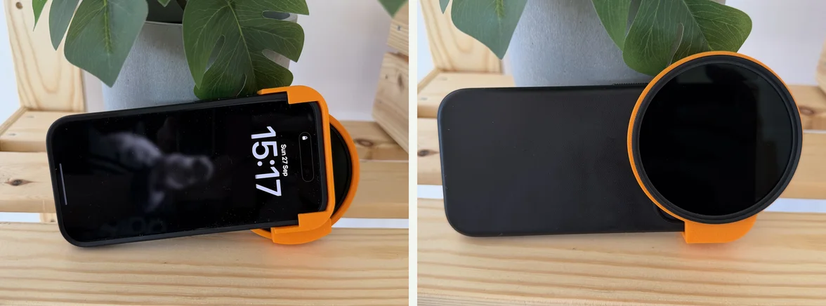
The printed mount on the phone: from the screen side, and from the back with the filter screwed in.
An AI model in Blender through an MCP server
I had never used Blender (a free 3D modeling program) before, and my 3D design experience stops at a few simple things made in an uncomplicated in-browser program, so I handed the design over to the model entirely. I worked with Claude Code (a personal preference, not a recommendation) and the Claude Opus 5 model, that is, with a cloud model, because long, multi-step reasoning about geometry is the kind of task where I reach for a frontier model without a second thought. The model operated Blender directly through a so-called MCP server, an add-on that lets a language model carry out operations in a program by itself: create solids, cut holes, measure distances and save finished files for printing.
The work was split like this: I described what I wanted to achieve and said what I would be printing on (a Bambu Lab P1S printer, ordinary PLA plastic), and the model fetched the technical drawings that Apple publishes for accessory makers (with the position of each camera and its field of view), designed the part, checked it and saved the files, which I opened in the printer's software and printed. My role between versions came down to what the model cannot do by itself in this setup: print the part, try it on the phone and describe in plain words what was wrong (“it touches the lens”, “it's too loose”, “it wobbles a bit”).
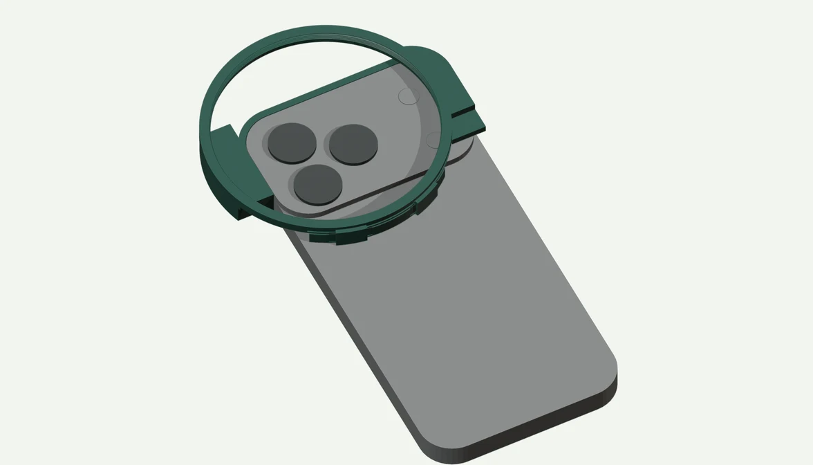
The mount in Blender, fitted on the phone model: the threaded ring for the filter surrounds all three cameras.
The first print: a thread test
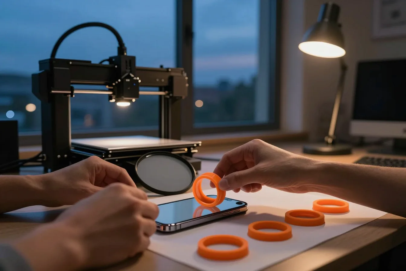
The most demanding element seemed obvious: the thread. Fractions of a millimeter matter there, and every printer prints a little differently, so instead of guessing how much clearance to leave, the model suggested that the first print should not be a part at all but a test: four threaded rings side by side, each with a slightly different clearance (from 0.10 to 0.25 mm) and each labeled with a number. I screwed the filter into each of them, chose the one it turned in best, and from then on the clearance was no longer an assumption but a number tested on my printer, with my filter. One quick print replaced several full parts, any of which could have turned out not to fit, and in my view it was the most sensible move in the whole project.
The second and third prints
The second print was two things at once: the holder alone without the ring (a small, quick print meant only to show whether the mount held the phone well) and the full mount with the thread. At first sight the result was contradictory, because the holder alone held tight but touched the lens, while the full mount cleared the lenses well but was too loose. The model found one cause for both observations, one I probably would not have spotted myself: the lenses stick out above the camera island more than it had assumed (that height is not on Apple's drawing), and the holder only seemed tight because it was resting on a lens that was pushing it apart. After the fix the third print fit and worked, and less than a day passed from the first message to a working part (with a night in between).
Where the model got it wrong
Then the refinement began, and here the model got it wrong a few times. I asked for the filter to be moved higher (to leave more room at the back for holding the phone) and for the ring to be joined to the mount on the other side, because it wobbled a little. The model calculated how high it could move the filter before the wide-angle camera started to see the edge of the ring in the frame, but it added the reinforcement on the wrong side, because I was looking at the part in the printer's software, which shows it turned around (the way it lies on the build plate), so what I called the right side was the left side for the model. When I asked for a support to rest the ring against the back of the phone, the support ended up hanging almost three millimeters above the glass, because the model read a dimension from Apple's drawing that looked like the length of the camera island but in fact described a zone that must not be covered with metal because of the antennas (15 mm longer than the island itself). Once, I stopped it before printing, because in a file it considered finished I noticed a thin beam floating in the air next to the part (a cutting error that its own checks had not caught). I spotted each of these errors myself, looking at the file or at the print, but each time it was the model that found the cause, and within minutes (in the case of the drawing it read the dimensions directly from the lines in the PDF file instead of from the number printed on it).
Errors turned into checks
What I find most interesting is what these errors left behind, because with them came more automated checks that the model runs on every new version: whether the file is a single solid body (added after the floating beam), whether the part intersects the phone anywhere, whether any camera sees the edge of the ring and, most important in my view, whether the part can be put on at all (a simulation of sliding the mount onto the phone step by step, every two millimeters). That last one caught a problem that does not show in the finished design: a part that fits perfectly once it is on catches on the lens on the way. When I wanted a wider and deeper support, it was this simulation that showed such a part would not go onto the phone, so instead of meeting the request at any cost, the model proposed a separate snap-on piece, fitted only after the mount has been slid on. Today the whole design builds with one command in about a minute, together with all the checks, so for the version for a leather case all I had to do was measure two dimensions with calipers, and the model recalculated the rest by itself (and that version also fits and works).
What a mistake costs
I would not want this text to suggest that the model replaces a designer. An experienced designer would probably have made this part faster and without many of these errors, and what a mistake costs also matters here: a dozen or so grams of plastic and some printer time, so I could afford to let the print be the test. If the same part were going into production, where one mistake means, for example, a new injection mold, there would have to be far more checks, and in my view someone experienced should review the design before anything is ordered.
The pattern itself seems useful to me beyond the phone and the filter: the model does the work in a program I don't know, the cheapest test happens at the very start (four rings instead of four full parts), a person steps in where hands and eyes are needed, and an error that slipped through once is, as far as possible, turned into a check so that it does not slip through a second time.
In short
- A language model can not only write but also operate a program (here Blender, which I had never used before) and hand back finished files, in this case for 3D printing.
- From the first message to a working part: three prints and less than a day.
- The cheapest step at the start: one test print instead of guessing how much clearance to leave in the thread.
- The model got things wrong (the wrong side, a misread dimension, a beam in the air): I caught the errors, and the model quickly found the causes.
- Errors turned into automated checks, so later versions come out faster and more reliably.
- How much checking you need depends on what a mistake costs.